Sabien Technology manufactures control systems that reduce energy waste in commercial and industrial heating plant. The company focuses on controls that improve the performance of boilers and direct fired hot water systems without altering the safety design of the equipment. Its primary products are the M2G Boiler Load Optimiser for space heating and the M1G controller for direct fired water heaters. Both are designed to cut unnecessary burner operation by identifying periods where a boiler fires without serving any real heating demand.
Energy waste in commercial plant is a constant problem because many boilers operate far below full load for long parts of the year. Buildings with multiple heating zones experience extended periods where system demand drops. Even during these quiet periods, boilers continue to fire in response to standing heat losses from the boiler casing or pipework. These losses accumulate across long operating hours and produce measurable fuel waste and carbon emissions.
The M2G and M1G units target this behaviour by analysing the thermal characteristics of each boiler. The controls determine whether the boiler should fire or remain in a hold state. They do not modify set points, safety circuits or time schedules. Their purpose is to calculate boiler load and prevent firing that serves no useful purpose. These systems are installed in facilities with high energy consumption. Typical applications include hospitals, manufacturing plants, universities, offices, distribution centres and public buildings where large heating boilers operate for extended periods.
Dry Cycling Explained
Dry cycling is one of the most common and most costly inefficiencies in commercial boiler plant. It occurs when a boiler fires even though the building is not calling for heat. These unnecessary firings happen because the boiler loses heat naturally through its casing, pipework and stored water volume. When this heat loss causes the temperature to fall to the thermostat’s switching point, the boiler fires again purely to top up its own internal heat. No heat is delivered to the building, and no occupants benefit from the energy consumed. The effect is most noticeable in sites with large boilers, oversized systems or long periods of light load.
Commercial boilers contain significant water volume, often several hundred litres. This water cools slowly, causing repeated and shallow temperature drops throughout the day. Each drop triggers a thermostat response, resulting in a firing cycle that replaces heat lost only to the plant room. Buildings with intermittent demand, reduced occupancy or mild outdoor conditions experience the highest levels of dry cycling, because true heating demand is low while standing losses continue.

Key characteristics of dry cycling:
• Firing without useful output: Burner activates only to replace heat lost from the boiler shell, not to heat the building.
• Triggered by stored water volume: Larger water content means longer cooldown periods and more frequent top-up firing.
• More common during low load: Occurs heavily during shoulder seasons, night-time operation and partial occupancy.
• Not prevented by standard controls: Thermostats respond only to temperature drops, regardless of whether the heat loss is useful or wasted.
Dry cycling directly increases fuel consumption and carbon emissions. Each unnecessary firing consumes gas or oil while delivering no thermal benefit to heating circuits. Over time, this behaviour also accelerates mechanical wear. Gas valves, fans, ignition transformers and flame monitoring systems accumulate run hours far beyond what is required to meet the building’s actual heating demand. This shortens component lifespan and raises maintenance frequency.
Traditional boiler controls cannot prevent dry cycling because they operate on basic temperature thresholds. When temperature falls below set point, the boiler fires. When temperature rises, it stops. These controls cannot distinguish between a real heat call from the system and simple standing losses from pipework, insulation gaps or boiler casing. Without additional logic to interpret thermal behaviour, the boiler continues to waste fuel through repetitive, low-value firing cycles.
How the M2G System Works
The M2G uses thermal analysis to distinguish real heating demand from standing losses. It measures the flow and return temperature of each boiler through two digital sensors fixed to the pipe surface. The controller records the rate of change in temperature over time and analyses the profile of the boiler during and after firing.
The core principle is simple. If a boiler cools slowly and returns to its thermostat threshold without any real change in return temperature, the system recognises that the firing request is not linked to building load. The controller places the boiler into a hold state called Save Mode. The boiler remains on standby until the system detects a thermal pattern that corresponds to real heat draw from the building. The controller learns the behaviour of each boiler by observing the temperature gradient. The gradient represents how the boiler cools when idle and how it warms when firing. The algorithm uses these patterns to decide when heat demand is genuine.

Save Mode prevents unnecessary firing by temporarily blocking the thermostat call. Once the profile matches real heating load, the controller releases the call and the boiler fires normally. This process repeats throughout the day and adapts continuously to changing system conditions. The controller works with single stage burners, high and low fire burners and boilers with modulating capability. It is also suitable for gas, oil and LPG fired systems and both condensing and non condensing units as long as the operating temperature does not exceed its rating. Commercial installations often record savings between ten percent and twenty five percent. Savings depend on boiler design, building type, system load and the extent of existing dry cycling.
Overview of M2G Hardware
The M2G control unit contains relay circuits, a processing board, LED indicators and connections for the flow and return sensors. The casing mounts on the boiler or on a nearby panel where it is visible to maintenance staff. LED indicators provide immediate feedback on operating conditions. The Power LED confirms that the unit is energised. The Stat On LED indicates that the boiler thermostat is calling for heat. The First Firing LED shows that the boiler is allowed to fire. The Stage Two Firing LED appears on multi stage burners. Combined, these indicators describe the entire state of the boiler and the controller.
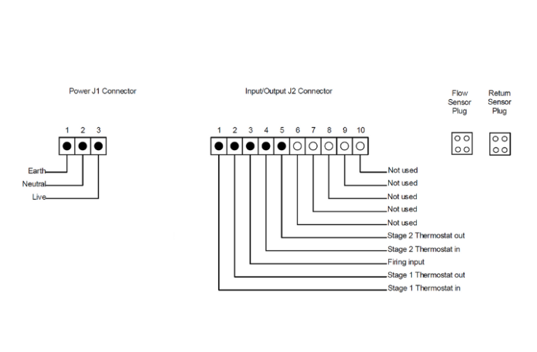
The internal relays are normally closed. They sit in series with the boiler thermostat circuit. This design ensures that if the controller loses power or fails, the boiler returns to its original control method without interruption. The safety circuits remain unaffected because the M2G never interacts with limit stats or lockout mechanisms. The temperature sensors attach to the outer surface of the flow and return pipes. They do not require pipework to be drained or cut. Their mechanical fixing method ensures accurate readings without introducing plumbing risk.
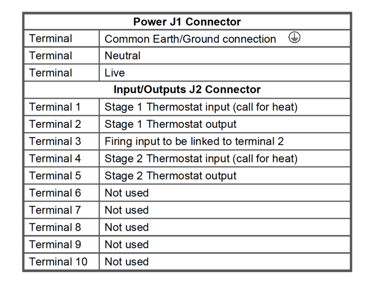
The fail safe design maintains boiler safety at all times. The thermostats remain connected even if the controller experiences a fault. This preserves compliance with boiler manufacturer requirements and regulatory standards.
Installation Requirements
The M2G must be installed on a boiler that is in full working order, with stable firing behaviour and functional thermostats, pumps, burners and control modules. Any faults must be corrected beforehand, because the controller relies on consistent thermal patterns to identify real demand. Existing control systems such as weather compensation, BMS scheduling, time clocks and sequencing must also operate correctly so that the M2G receives clean, predictable call-for-heat signals. The electrical supply must match the unit’s rated voltage, remain stable and include a verified earth bond to prevent signal noise that could affect relay operation or sensor readings.
Environmental conditions must support accurate measurement. The mounting location must stay within the controller’s temperature tolerance and remain free of moisture, steam leaks and vibration. Heat-resistant multi-core cable must be used for all connections. The unit must be positioned where LED indicators are visible without removing boiler panels, as these LEDs are essential for commissioning and troubleshooting. All wiring must follow local regulations and be routed neatly away from high-voltage cables or hot components to preserve long-term reliability.
Engineering Parameter Table for M2G Installation
| Category | Engineering Parameter | Typical Value / Requirement | Why It Matters (Technical Explanation) |
|---|---|---|---|
| Thermal Behaviour | Minimum ΔT recognition threshold | 0.5°C to 1.0°C temperature drop rate | Below this gradient, cooling resembles standing loss rather than real load. |
| Sensor thermal lag | < 3 seconds | Ensures accurate detection of return-line cooling during transitions. | |
| Flow/return pipe material compatibility | Copper, steel, stainless | Maintains stable surface temperature for reliable sensor readings. | |
| Electrical Integrity | Relay switching tolerance | Zero-volt dry contact | Prevents interference with thermostat logic or BMS control paths. |
| Acceptable supply fluctuation | ±10 percent of rated voltage | PCB stability requires tight voltage control to avoid timing drift. | |
| Ground impedance | < 1 ohm | Reduces electromagnetic noise that can cause false Stat On readings. | |
| Signal Reliability | Maximum allowable control-loop latency | < 200 ms relay response | Ensures firing release aligns with true load conditions. |
| BMS signal isolation level | Must be volt-free | Prevents back-fed signals from simulating false heat demand. | |
| Interlock loop resistance | Must be near zero | High resistance introduces partial signals that confuse firing logic. | |
| Environmental Conditions | Maximum casing temperature | 50°C continuous | Protects PCB components from thermal ageing and voltage drift. |
| Humidity tolerance | < 90 percent non-condensing | Prevents sensor degradation and corrosion of PCB tracks. | |
| Vibration threshold | < 2 mm displacement | Ensures sensors retain contact with pipe and terminals don’t loosen. | |
| Sensor Physics | Sensor contact pressure | Firm mechanical contact | Prevents micro-gaps that create thermal lag or false gradients. |
| Insulation thickness after fitting | Equivalent to pipe insulation | Maintains stable readings by preventing ambient heat gain/loss. | |
| Distance from heat sources | > 150 mm from flues or burners | Avoids radiant heat corruption of return-line temperature readings. | |
| System Interaction | Boiler water content requirement | Medium or high | High thermal mass increases dry-cycle events, improving optimisation potential. |
| Ideal ΔT for algorithm learning | 8°C to 20°C between flow & return | Provides a clear temperature signature for load profiling. | |
| Sequencer compatibility | Works in series | Maintains correct boiler rotation without altering lead/lag control. | |
| Commissioning Expectations | Learning period duration | First 1–3 firing cycles | Controller builds baseline thermal behaviour before activating Save Mode. |
| Normal Save Mode frequency | Higher during mild weather | Indicates correct detection of standing heat losses. | |
| Expected LED sequence during faults | Static Power LED + no Stat On | Suggests upstream thermostat or BMS logic issue. |
Installation Process
The installation begins with fixing the wiring base in a stable position. The mounting surface must support the controller without vibration, movement or thermal expansion that could loosen fixings over time. It must also be checked for hidden conduits, steam lines or electrical trays to prevent accidental damage during drilling. When the base is mounted directly onto boiler casing, the boiler must be correctly bonded to earth. Bonding prevents electrical noise travelling through the casing, which protects the controller’s relay logic from interference and ensures accurate temperature sampling from the sensors.
Cable selection is determined by the plant room environment. Temperatures near boilers can remain high for long operational periods. For this reason, heat-resistant multi-core cable is used between the controller and the boiler thermostat circuits. This prevents insulation breakdown and maintains stable electrical performance throughout the life of the installation. Cable routing must avoid flues, burner housings and pump motors, all of which produce heat or electromagnetic interference.
The control unit is positioned next. It must be installed where engineers can see all LED indicators without removing covers or access panels. LED visibility is essential because commissioning, routine checks and fault-finding rely heavily on understanding the controller’s visual signals. The position should also allow access to terminal blocks for future service work.
Flow and return sensors are then installed. These sensors must sit firmly on the pipe surface, using the correct clamping or banding method supplied by the manufacturer. Accurate thermal contact is essential because the M2G’s temperature analysis depends on clean, undistorted readings. Once the sensors are secured, pipe insulation is reinstated to prevent ambient air or radiant heat from affecting the temperature gradient.
Correct sensor placement avoids:
• Temperature drift caused by radiant heat from flues or burner housings
• False temperature patterns from pump discharge turbulence
• Slow response times caused by partial insulation or poor pipe contact
The next stage involves routing the thermostat circuits through the M2G relay terminals. The boiler’s original call-for-heat line is removed from its existing position and re-routed through the M2G’s input and output terminals. This step must maintain full integrity of all OEM safety circuits. The installer performs continuity checks to verify that the relay opens and closes cleanly, confirming that the boiler responds correctly when demand is passed through the controller.
Before powering the unit, the installer verifies:
• Tight, secure terminal connections
• Correct polarity of thermostat in/out links
• Proper earth bonding and grounding
• Flow and return sensors firmly mounted and insulated
• Cables routed safely, away from high-temperature surfaces
• Controller location unobstructed and visible
Once these checks are complete and the installation is confirmed safe, the system is energised. The engineer then proceeds with commissioning to verify that LED behaviour, relay switching and sensor readings match expected operating patterns.
Wiring Configurations
Wiring the M2G correctly is essential because every firing decision depends on accurate thermostat signals and clean relay switching. The controller does not interfere with safety circuits, so the wiring must preserve all manufacturer protections while placing the M2G relay in the correct position within the boiler call-for-heat loop.
1. Single-Stage Burner Wiring
A single-stage burner uses one thermostat circuit. The M2G relay is installed in series with this circuit:
- Stage 1 Thermostat Input (Terminal 1) receives the call-for-heat from the boiler thermostat or BMS relay.
- Stage 1 Thermostat Output (Terminal 2) sends the call onward toward the burner control when the M2G authorises firing.
The controller monitors flow and return temperatures continuously. When Save Mode activates, the relay opens and interrupts the call-for-heat signal. When a real load is detected, the relay closes and restores the firing path.
This configuration prevents dry-cycle firing without altering any existing boiler safety or limit controls.
Common single-stage issues include:
- Thermostat signal connected to the wrong terminal
- Boiler high-limit thermostat wired before the M2G instead of after it
- External controls feeding the wrong side of the relay
- Back-feed voltage entering terminal 1 from a BMS system
All of these faults cause false LED indications or a boiler that fires once then locks out.

2. Two-Stage Burner Wiring
Two-stage burners use two independent thermostat circuits. The M2G must be wired so that stage one and stage two signals pass through the correct relay outputs:
- Stage 1: Terminals 1 → 2
- Stage 2: Terminals 4 → 5
Stage one must always energise before stage two.
Incorrect sequencing leads to:
- Stage two activating without stage one
- Premature high-fire operation
- Burner lockouts caused by missing interlocks
- LED patterns that do not align with operating conditions
The wiring must respect the burner’s high-fire/low-fire logic. Stage two output is only permitted when the boiler is under genuine load and the M2G temperature analysis authorises high-fire.

3. Interlocks and Control Logic
Interlocks play a critical role in commercial boiler protection. They must be placed in positions where the M2G can interrupt the thermostat demand, not the safety chain.
Correct placement ensures:
- No voltage feedback into the M2G input
- Accurate LED behaviour
- Clean relay operation
- No bypassing of manufacturer limit controls
- Full integrity of BMS firing logic
Incorrect placement produces predictable faults:
- Save Mode never activating
- Boiler firing once then stopping
- Stat On LED lighting without a valid demand
- Relay clicking without actual burner response
Back-feeding often comes from a BMS relay wired after the M2G instead of before it. In these cases, the M2G receives both a supply and a return signal simultaneously, interpreting it as a false call-for-heat.
Functional Modes and LED Operation
The M2G communicates its operating state through four key LEDs. Each indicator reflects a specific part of the boiler control sequence, making it possible to understand system behaviour at a glance.
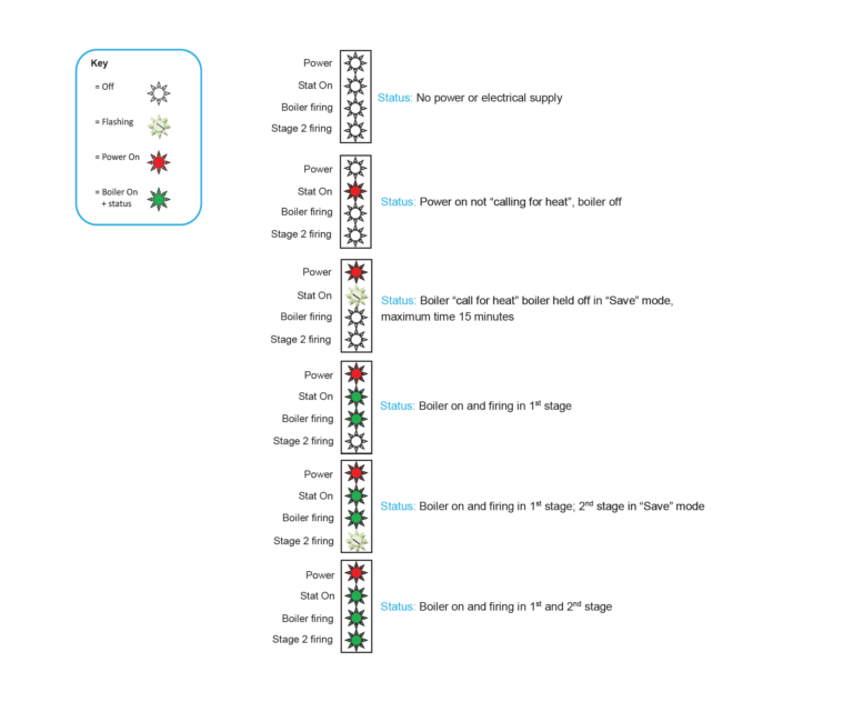
The Power LED confirms that the controller is receiving a stable supply. If this LED is off, the unit has no electrical feed or the internal fuse has failed.
The Stat On LED indicates that the boiler thermostat is issuing a call for heat. When this LED is solid, the controller recognises the signal and begins analysing the flow and return temperatures to determine whether a genuine heating load exists.
The Boiler Firing LED activates only when the M2G has confirmed real demand. At this point the relay closes, allowing the burner to enter the first firing stage. This LED offers a direct visual confirmation that the controller has validated the temperature pattern as genuine load rather than standing heat loss.
For boilers equipped with a second firing stage, the Stage Two Firing LED shows when the burner advances to high fire. This helps engineers distinguish between low-fire operation, high-fire demand, and transitions between the two.
Save Mode occurs when the thermostat requests heat but the measured temperature pattern does not match genuine load. The Stat On LED flashes to show that the controller is deliberately holding off the burner. The firing LEDs remain off during this period. Save Mode ends automatically once the controller detects a temperature profile consistent with real heat demand.
During initial power-up, all LEDs illuminate briefly. This is the controller’s built-in self-test sequence, confirming that the PCB, sensors and relay logic have initialised correctly.
Commissioning Procedure
Commissioning begins by applying power to the M2G and confirming that all LEDs illuminate briefly during the self-test. The Power LED must remain steady, and the Stat On LED must respond when the boiler thermostat calls for heat. Once this is confirmed, the boiler thermostat is cycled to trigger the first firing. The boiler fires normally on this run because the controller is learning the boiler’s temperature pattern.
The thermostat is cycled again after the initial learning period. At this point, Save Mode should activate. The Stat On LED flashes to show that the controller is holding the firing relay while it checks whether the drop in return temperature matches real demand. When the thermal pattern confirms genuine load, the firing LED activates and the burner is released.
On two-stage systems, the engineer checks the Stage Two Firing LED by raising demand and then reducing it to return to low fire. This confirms correct wiring of T1 and T2 and proper detection of both firing stages.
Key confirmations during commissioning include:
- LED behaviour matching thermostat calls
- Accurate sensor readings on flow and return
- Correct transition between firing stages
- Save Mode activation at the expected point
The boiler is then isolated and powered back up. The commissioning sequence is repeated to ensure consistent behaviour. Any unexpected LED pattern indicates wiring errors, reversed sensors or incorrect thermostat routing that must be corrected before handover.
Real World Operating Behaviour
In day-to-day use, the M2G continuously adapts to changes in building load. Save Mode appears frequently during mild or transitional weather because the system requires little heat and many thermostat calls represent residual standing losses rather than true demand. When load increases, Save Mode reduces naturally because temperature trends show consistent energy draw, allowing the boiler to fire normally and maintain comfort levels across occupied spaces.
During low load, the controller monitors the temperature pattern on the return line and assesses whether the cooling rate matches a genuine call for heat. If the rate of change suggests the building is still satisfied, M2G holds the boiler to prevent a false firing cycle. When the return temperature drops in a profile that is characteristic of real demand, the controller releases the burner. This behaviour reduces short-cycling and stabilises heat distribution during periods when heating loads fluctuate.
Under high load, the controller recognises a strong and continuous call for heat. In these conditions, the boiler fires immediately because the data confirms that demand is genuine. Heating zones operate normally, circulation remains steady and the system delivers consistent temperature control across large commercial spaces.
The return temperature profile becomes noticeably smoother once M2G is installed. The boiler no longer produces rapid, shallow cycles caused by standing heat loss. Instead, the firing pattern aligns with actual system need, reducing hydraulic disturbance, improving system balance and supporting more efficient heat transfer throughout the plant.
Troubleshooting Guide
1. Unit Has No Power
Loss of power to the M2G usually points to an interruption in the supply path. Checks include verifying live voltage at the input terminal, continuity of the neutral conductor, and correct earth bonding. The internal fuse (F1) must also be inspected. A blown fuse typically indicates either a wiring short or an overcurrent event on the PCB. If live, neutral and fuse conditions are correct, the PCB itself may have failed.
2. Boiler Does Not Fire
If the M2G has power but the boiler remains inactive, the first point of inspection is the live feed entering the T1 thermostat input. A missing call for heat signal prevents the system from initiating the firing sequence. High-limit temperature cut-outs must be reset, and time clocks, BMS schedules and external interlocks must be confirmed, as any of these can hold the boiler off even if the M2G is operating correctly.
3. Boiler Fires Once and Stops
When the burner fires during the first firing cycle but fails to refire afterwards, this usually indicates incorrect wiring on T1 and T2, or interference from another device in the control chain. In this condition the M2G may not correctly detect the return of the demand signal. The Stat LED is the key indicator: if it flashes when it should remain solid, the controller interprets that the boiler is in Save Mode instead of receiving a genuine call for heat.
4. Save Mode Never Activates
If the boiler repeatedly fires without ever entering Save Mode, the M2G may not see the expected temperature pattern. Incorrect sensor placement, reversed flow and return sensors or poor thermal contact will prevent the algorithm from validating standing heat loss. Systems operating under continuous heavy load will also have limited Save Mode opportunities. Wiring errors where the thermostat signal bypasses the M2G can cause the controller to miss the call entirely.
5. Incorrect LED Behaviour
Unexpected LED combinations usually point to wiring faults. Voltage back-feeds from mis-positioned interlocks or BMS relays can simulate a permanent call for heat or permanent firing state. Confirm that the M2G is placed correctly in series with the control signal, and not in parallel with external devices. Correct relay sequencing restores normal LED logic.
6. Back Feed or False Signalling
False signalling occurs when external controls inject voltage into the M2G’s thermostat loop. This often happens with poorly isolated BMS outputs or shared neutral paths. The result is unreliable firing, LED inconsistencies or Save Mode bypassing. Identifying the source of the back feed and rerouting or isolating the circuit resolves the issue.
7. Diagnostic Tools and Methods
A multimeter is the primary diagnostic tool. Voltage tests confirm power supply integrity and correct thermostat feed behaviour. Continuity tests ensure that relay contacts open and close as designed. Temperature sensors should be checked for correct values during heating and cooling cycles to verify accurate detection of flow and return changes. Boiler thermostats can be tested individually to confirm switching accuracy and eliminate the thermostat as a source of intermittent faults.
Maintenance and Long-Term Reliability
The M2G requires no calibration because its operation is handled entirely by solid-state electronics. With no mechanical components, long-term degradation is minimal and maintenance centres on physical condition rather than performance adjustment. Engineers verify enclosure integrity, check for heat exposure and confirm that relay terminals remain secure. Sensor accuracy governs optimisation performance, so both flow and return sensors must remain tightly fixed to the pipe surface with insulation fully reinstated. Any cable damage or poor contact alters temperature readings and disrupts the controller’s ability to analyse thermal patterns. Internal fuses protect against electrical surges, and replacement must only occur after the source of the fault is identified to prevent repeated PCB stress.
Maintenance visits often uncover installation-related issues instead of device failure. These findings must be corrected immediately to restore proper logic, prevent false Save Mode behaviour and preserve boiler safety. The device typically remains operational for many years, often outlasting auxiliary controls such as sequencers and BMS relay modules.
Key Maintenance Actions
Verify enclosure condition and mounting security.
Confirm relay terminals are tight and free from oxidation.
Inspect flow and return sensors for:
• Correct pipe contact
• Full insulation coverage
• No cable damageCheck internal fuse integrity and investigate the root cause of any failure.
Inspect thermostat wiring for shorts, loose conductors or shared neutrals.
Confirm interlocks are correctly positioned in the call-for-heat path.
Review cable routing to avoid electrical noise from high-voltage conductors.
Validate correct sensor orientation (flow vs return).
Record operating LED patterns to confirm stable logic over time.
Benefits of the M2G System
The M2G reduces wasted boiler firing by preventing cycles triggered only by standing heat loss. Each avoided cycle translates to measurable reductions in gas or oil consumption. Fuel savings typically fall between 10 and 25 percent, depending on boiler size, operating hours and system demand.
Burner assemblies last longer because unnecessary firing is removed from daily operation. Ignition transformers, gas valves, modulating motors, fans and flame-sensing components all experience fewer run hours. This reduction in mechanical stress extends service life and lowers maintenance frequency.
Plant performance becomes more stable. Flow and return temperatures settle into a predictable pattern because firing events occur only when the building generates genuine load. The result is better comfort control and improved heat distribution across the system.
Safety is unchanged. The M2G does not alter, bypass or interfere with OEM safety devices. High limit stats, pressure switches, flame safeguards, lockout controls and BMS interlocks continue to operate in their original configuration.
The system is adaptable across most commercial boiler platforms. It operates correctly on:
- Condensing and non-condensing boilers
- Single-stage, two-stage and high/low fire burners
- Gas, oil and dual-fuel appliances
- Boilers controlled by standalone stats or integrated BMS systems
Additional advantages include:
- Lower carbon emissions due to reduced gas or oil consumption
- More predictable boiler behaviour, which simplifies maintenance planning
- Improved return temperature consistency, supporting system balance
- Zero impact on building set points, thermostats or comfort levels
- No change to hydraulic design, pipework or flow rates
The result is a cleaner, more efficient boiler plant that delivers reliable savings without modifying the boiler’s safety chain, combustion process or programmed set points.
Explore Our Services Here!
- Commercial Gas Boiler Services
- BMS Services
- Commercial Boiler Pump Services
- Gas Purging Services
- Commercial Kitchen and Gas Catering Engineers
- Water Booster Pump Services
- Pressure Testing Services
- Gas Safety Certificate CP42
- Block Managed Heating Systems
- Heat Interface Unit Services
- Air Source Heat Pump Services
The Sabien Technology M2G gives commercial boiler plant a measurable efficiency advantage by analysing flow and return temperatures to stop firing events that deliver no useful heat. This approach reduces fuel use, lowers carbon output and cuts unnecessary wear on burner components. The controller preserves all OEM safety circuits, set points and BMS logic, allowing it to operate as a non-intrusive optimisation layer that improves boiler behaviour without altering the plant’s original design.
Across hospitals, schools, industrial facilities and offices, the M2G delivers stable temperature patterns, fewer ignition cycles and more predictable system performance. Its LED feedback, relay logic and sensor arrangement make commissioning and maintenance straightforward. When correctly installed, the device provides long-term savings, smoother system operation and consistent comfort levels, making it a reliable upgrade for modern boiler efficiency.
Frequently Asked Questions
The controller studies how the boiler heats and cools over time. It compares this pattern to the return-temperature behaviour seen during real demand. If the profile does not match the building’s load signature, the M2G holds the burner in Save Mode until the data confirms a true heat requirement.
Yes. The M2G sits only in the thermostat path and does not interfere with modulation, sequencing or weather compensation. These controls continue to function normally. The device responds to whatever demand signal they generate and optimises only the firing cycle logic.
No. The sensors mount externally on the pipe surface, and no mechanical work is required. There is no draining, cutting or breaking into the heating circuit. All optimisation is performed through thermal data rather than flow restriction or valve manipulation.
The algorithm immediately loses its ability to interpret the boiler’s behaviour. The system defaults to fail safe, restoring full thermostat control to ensure uninterrupted heating. Sensor faults typically present as erratic LED behaviour or loss of Save Mode activation.
In buildings with consistently high heat demand, Save Mode activates infrequently. The controller still monitors the temperature pattern, but genuine load keeps the boiler firing normally. The device remains useful because it prevents dry cycling during off-peak periods.
Yes. Electrical interference can distort relay operation and LED signalling. Proper earthing and the use of heat-resistant, shielded or well-routed cable prevent noise from entering the thermostat loop, ensuring stable logic and reliable Save Mode decisions.